Ultra-wideband (also known as UWB, ultra wideband, ultra-wide band and ultraband) is a radio technology that can use a very low energy level for short-range, high-bandwidth communications over a large portion of the radio spectrum. UWB has traditional applications in non-cooperative radar imaging. Most recent applications target sensor data collection, precision locating and tracking applications.
Due to low emission levels permitted by regulatory agencies, UWB systems tend to be short-range indoor applications. UWB is used for real-time location systems, its precision capabilities and low power make it well-suited for radio-frequency-sensitive environments, such as hospitals.
UWB has been a proposed technology for use in personal area networks, and appeared in the IEEE 802.15.3a draft PAN standard. However, after several years of deadlock, the IEEE 802.15.3a task group was dissolved in 2006. The work was completed by the WiMedia Alliance and the USB Implementer Forum. Slow progress in UWB standards development, the cost of initial implementation, and performance significantly lower than initially expected are several reasons for the limited use of UWB in consumer products (which caused several UWB vendors to cease operations in 2008 and 2009).
Ultra-wideband was formerly known as pulse radio, but the FCC and the International Telecommunication Union Radiocommunication Sector (ITU-R) currently define UWB as an antenna transmission for which emitted signal bandwidth exceeds the lesser of 500 MHz or 20% of the arithmetic center frequency. Thus, pulse-based systems—where each transmitted pulse occupies the UWB bandwidth (or an aggregate of at least 500 MHz of narrow-band carrier; for example, orthogonal frequency-division multiplexing (OFDM))—can access the UWB spectrum under the rules. Pulse repetition rates may be either low or very high. Pulse-based UWB radars and imaging systems tend to use low repetition rates (typically in the range of 1 to 100 megapulses per second).
On the other hand, communications systems favor high repetition rates (typically in the range of one to two gigapulses per second), thus enabling short-range gigabit-per-second communications systems. Each pulse in a pulse-based UWB system occupies the entire UWB bandwidth. This allows UWB to reap the benefits of relative immunity to multipath fading, unlike carrier-based systems which are subject to deep fading. However, both systems are susceptible to intersymbol interference.
A significant difference between conventional radio transmissions and UWB is that conventional systems transmit information by varying the power level, frequency, and/or phase of a sinusoidal wave. UWB transmissions transmit information by generating radio energy at specific time intervals and occupying a large bandwidth, thus enabling pulse-position or time modulation. The information can also be modulated on UWB signals (pulses) by encoding the polarity of the pulse, its amplitude and/or by using orthogonal pulses. UWB pulses can be sent sporadically at relatively low pulse rates to support time or position modulation, but can also be sent at rates up to the inverse of the UWB pulse bandwidth.
A valuable aspect of UWB technology is the ability for a UWB radio system to determine the "time of flight" of the transmission at various frequencies. This helps overcome multipath propagation, as at least some of the frequencies have a line-of-sight trajectory. With a cooperative symmetric two-way metering technique, distances can be measured to high resolution and accuracy by compensating for local clock drift and stochastic inaccuracy.
Another feature of pulse-based UWB is that the pulses are very short (less than 60 cm for a 500 MHz-wide pulse, and less than 23 cm for a 1.3 GHz-bandwidth pulse) – so most signal reflections do not overlap the original pulse, and there is no multipath fading of narrowband signals. However, there is still multipath propagation and inter-pulse interference to fast-pulse systems, which must be mitigated by coding techniques.
In the USA, ultra-wideband refers to radio technology with a bandwidth exceeding the lesser of 500 MHz or 20% of the arithmetic center frequency, according to the U.S. Federal Communications Commission (FCC). A February 14, 2002 FCC Report and Order authorized the unlicensed use of UWB in the frequency range from 3.1 to 10.6 GHz. The FCC power spectral density emission limit for UWB transmitters is −41.3 dBm/MHz. This limit also applies to unintentional emitters in the UWB band (the "Part 15" limit). However, the emission limit for UWB emitters may be significantly lower (as low as −75 dBm/MHz) in other segments of the spectrum.
Deliberations in the International Telecommunication Union Radiocommunication Sector (ITU-R) resulted in a Report and Recommendation on UWB in November 2005. UK regulator Ofcom announced a similar decision on 9 August 2007. More than four dozen devices have been certified under the FCC UWB rules, the vast majority of which are radar, imaging or locating systems.
The communication chip currently used by our company supports six frequency bands from 3.5GHz to 6.5GHz, supports three data transmission rates of 110 kbps / 850 kbps /6.8 Mbps, and the maximum length of a single packet can reach 1023 Byte.
The following figure shows the UWB channels in IEEE802.15.4-2011 supported by the communication chip
UWB Channel Number | Center Frequncey (MHz) | Band(MHz) | Bandwidth(MHz) |
1 | 3494.4 | 3244.8~3744 | 499.2 |
2 | 3993.6 | 3744~4243.2 | 499.2 |
3 | 4492.8 | 4243.2~4742.4 | 499.2 |
4 | 3993.6 | 3328~4659.2 | 1331. 2* |
5 | 6489.6 | 6240~6739.2 | 499.2 |
7 | 6489.6 | 5980.3~6998.9 | 1081.6* |
The following figure illustrates the data rate and PRF (pulse repetition frequency) in IEEE802.15.4-2011 supported by the communication chip
PR* (MHz) | Data Rate (Mbps) |
16 | 0.11 |
16 | 0.85 |
16 | 6.81 |
64 | 0.11 |
64 | 0.85 |
64 | 6.81 |
The following figure shows the specifications of the UWB chip of the company and the specifications used
& style="font-size: 20px;" style="font-size:24px;font-family:標楷體">
Item | Description | Remarks |
Standard | IEEE802.15.4-2011 | |
Frequency band | 3.5GHz~6.5GHz Channel 1:3.25GHz~3.75GHz Channel 2:3.75GHz~4.25GHz Channel 3:4.25GHz~4.75GHz Channel 5:6.25GHz~6.75GHz | Default use 4GHz Channel2:(3.75GHz~4.25GHz) |
Channel frequency width | 500 MHz | |
Rate | 110Kbps/850Jbps/6.8Mbps | Default use 6.8Mbps |
Output power | Max -30dBm/MHz | 0dB -30.5db Software editable |
Modulation mode | BPM with BPSK | |
FDMA | 4 channels | |
CDMA | 2 different code / channel | |
Working Mode | Time of flight(TOF) | |
Communication range | UP to 60M(Max) outdoor With PA Can to 200M(Max) |
The figure below illustrates the numerical adjustment method of the transmit power, which can be divided into seven levels of 3dB coarse adjustment and 32 levels of 0.5dB fine adjustment. The maximum transmit power can be set to 33.5dB
< src="http://www.dmatektw.com/dmadoc/Public/DocPic/Book-UWB-IPS/Pic1/004.png" title="1603358463947061.png" alt="1603358463947061.png" style="width: 363px; height: 362px;" width="363" vspace="0" height="362" border="0"/>
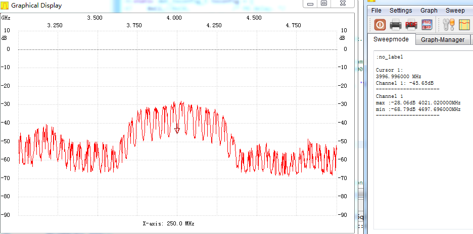
The figure below shows the results of our company's testing of different transmission powers on the channels used by the standard UWB modules. The standard equipment will use channel 2 for communication, and channel 1 for settings and firmware updates.
TX power -0x67676767(12.5dB)
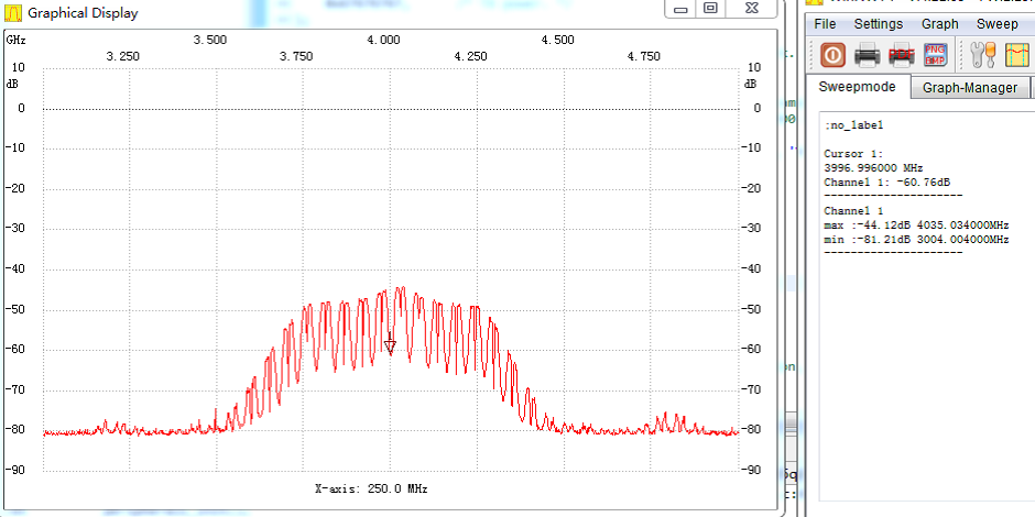
TX power -0x47474747(15.5dB)
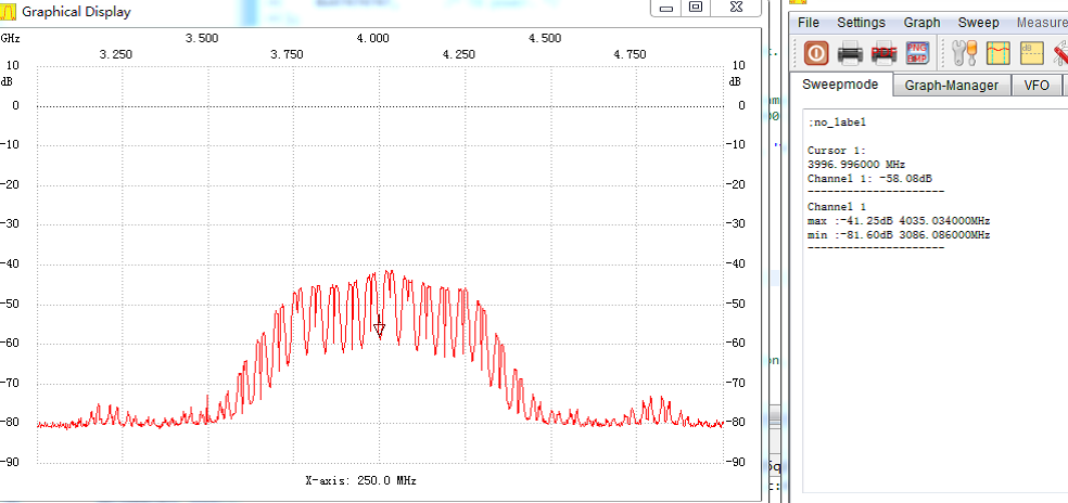
TX power -0x27272727(18.5dB)
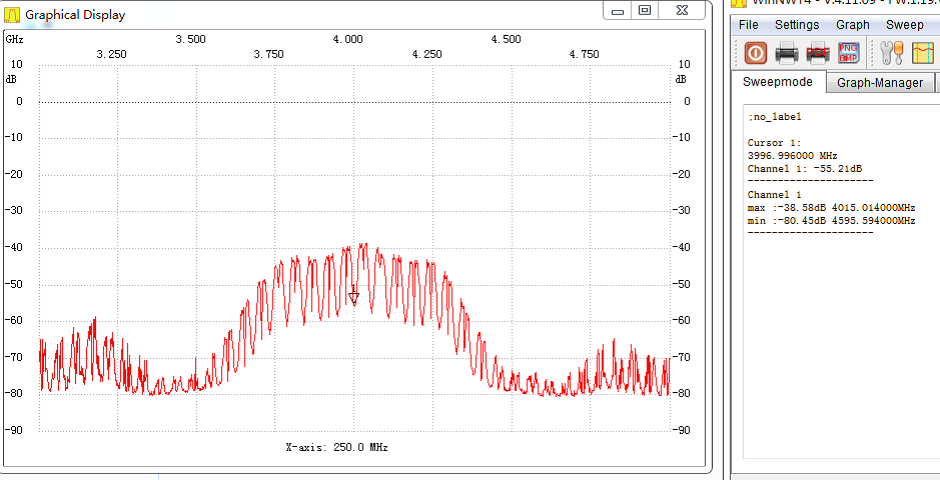
TX power -0x07070707(21.5dB)
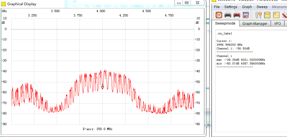
TX power -0x2D2D2D2D(21.5dB)
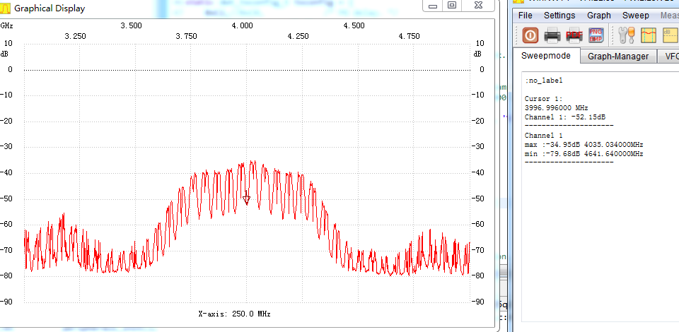
TX power -0x33333333(24.5dB)
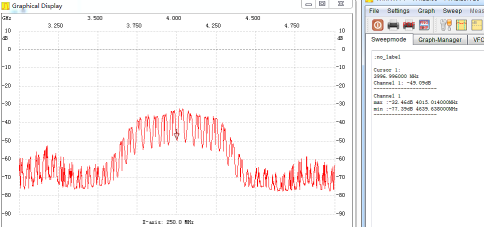
TX power -0x39393939(27.5dB)
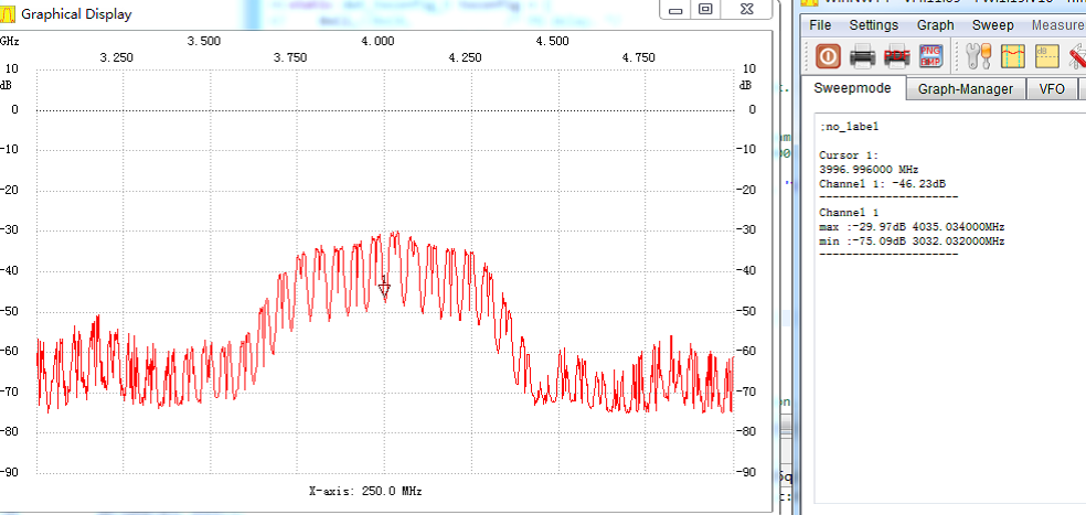
TX power -0x3F3F3F3F(30.5dB)

TX power -0x1F1F1F1F(33.5dB)
<>