The following figure shows the basic structure of the positioning system.
Methods of Positioning Communication
1. Tag sends broadcast packet to get distance information from Anchor (TOF)
2. Tag collects up to five sets of distance information from the surrounding Anchor (filtered based on factors such as distance and signal)
3. Tag sends positioning packet to Anchor (packet content includes Tag ID, distance, power and other information)
4. Anchor forwards the positioning packet to the specified server IP and server communication port
5. The monitoring software running on the server receives the positioning packet and calculates the positioning coordinates
Methods of Network Communication
1. The anchor and server communicates using Socket to transfer UDP packet
2. Transfer positions via customized packet format and its control
3. Requires the server IP and communication port of specified anchor equipment
4. The anchor connects to internet via WiFi and wired internet
Secondary Development of the Positioning System
1. Provides network communication protocol and packet format
2. Provides positioning software C# source code
3. DII provides functions such as network monitoring, initialization of device configuration, coordinate calculation, sound control etc.
A、 UWB Positioning Architecture
UWB precise positioning network structure is divided into two parts, one is the UWB device communication of the positioning equipment, the other is network packet transfer. This introduction would be based on the network part. We would briefly introduce this two network structure below to help the users build a basic understanding to the precise positioning system.
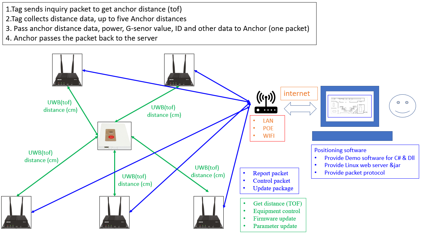
a. UWB network communication structure, UWB network communication divided into two parts
● Positioning operation: While UWB positioning is operating, Tag would send a UWB broadcasting packet to the surrounding anchors. After anchors receive this enquiry packet, they will respond a relative UWB packet to Tag which it will used to to calculate and obtain the distance between itself and the anchor, this is called Time-of-flight (TOF), this process will not take more than 10 ms. After obtaining the distance, Tag use the shortest distance and signal quality as determination conditions to send maximum five distance information of anchors to the positioning software. The anchor that sends packet will be the one that has the best signal or is available determined by Tag.
● Device parameter and firmware update: UWB precise positioning system contains online parameter and firmware update mechanism. Some anchors can directly communicate with positioning software and update via internet, while others will not directly communicate with positioning system and the updated information will be temporary saved in anchor. Hence, UWB Tag will enquire anchor periodically whether the software or parameter is updated. They send an enquiry packet every twenty minutes, because when device is powered on it will send an enquiry packet, user can directly power on to speed up this update time
b. Network packet transfer structure, we are using socket protocol to send UDP packet to communicate with the positioning software of the server side. The key here is that positioning software and anchor has to be able to communicate normally, if after anchor is turned on and it failed to find the server computer of the positioning software, the device function may not work normally. There are mainly three UDP packet for transfer in the network:
● Anchor reports packet periodically
● Positioning packet of Tag sent to positioning software via anchor
● Parameter and firmware update packet is set to server via setting software
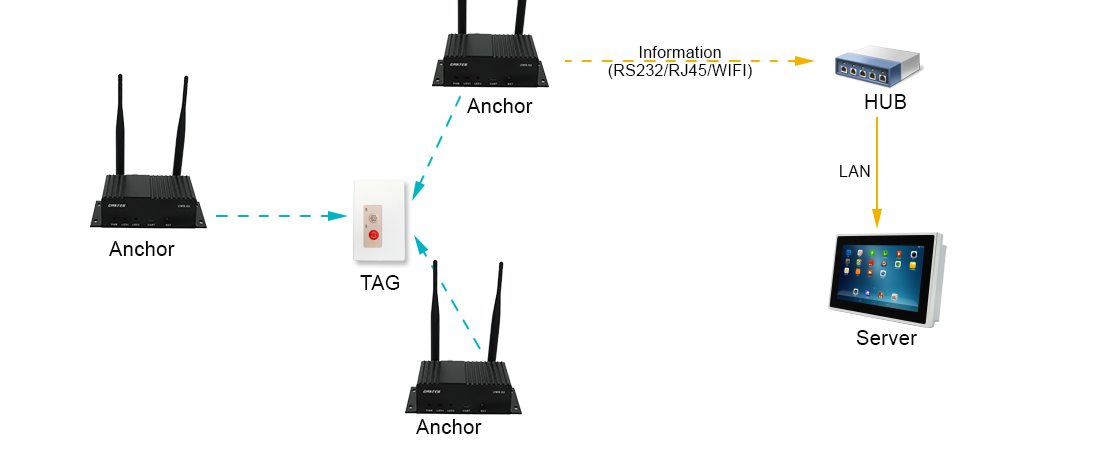
Note that another active positioning method does not send positioning packets through the network, but transmits data through a serial port as shown in the figure below
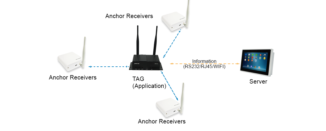
Active positioning in the UWB network communication architecture is the same as the standard version, except that the tag is replaced with a device with UART such as UWB-02, which is suitable for robots, AGVs, and other applications that have a CPU host as the processor.
Tag Output Interface
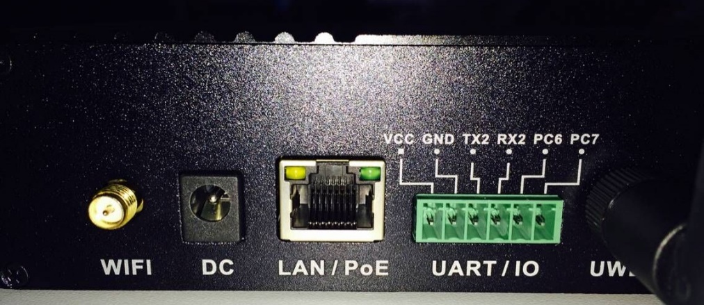
Tag positioning information is output through TX2 in the UART/IO port near the antenna. The signal is TTL level, and it needs to be connected to a PC with an external TTL-USB or TTL-232.
Tag GND <——> Conversion Cable - GND
Tag TX2 <——> Conversion Cable - RX
B、 Cross-Domain Architecture
Letʻs look at the connection status of different domain
For example:
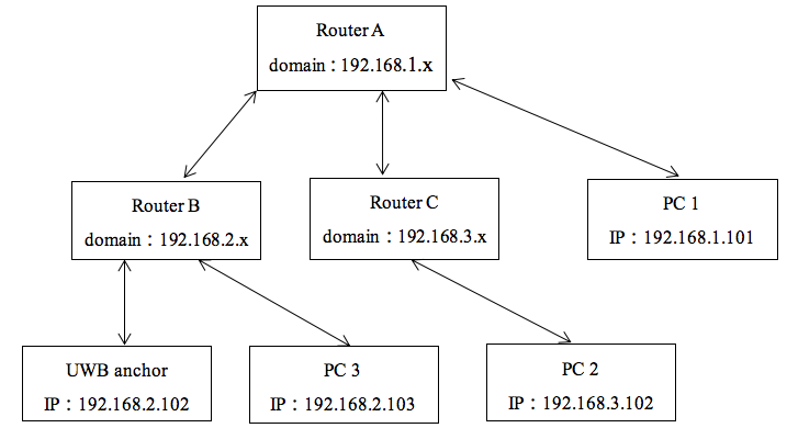
There are three routers in this scenario, Router A is at the top with domain 192.168.1.1, it is connected to two routers – Router B and C, which has domain 192.168.2.x and 192.168.3.x respectively.
● A UWB positioning anchor is connected to router B and its IP is 192.168.2.102
● There is a PC2 connected to Router C, its IP is 192.168.3.102
● There is a PC1 connected to Router A, its IP is 192.168.1.101.
● There is a PC3 connected to Router B, its IP is 192.168.2.103
This scenario could lead to possibly three network structure:
Scenario 1:
PC3 as Server PC, UWB Anchor and PC3 is under the same domain, positioning software can directly receive location
Scenario 2
PC1 is the Server PC, and PC1 is under the router on the upper layer of UWB Anchor. In this situation, Router B will not recognize the IP of PC1 and may not be able to communicate.
However, some routers will send unknown IP to the upper layer, in this case the packet can be sent to PC1 smoothly. If the network architecture is in this situation, the user first asks the MIS or the information department to evaluate whether routing table settings or forwarding settings are required. We would suggest to consider the independent network in the first situation as the positioning network.
Scenario 3
PC2 is the Server PC, PC2 and UWB Anchor are under different routers, and the two routers are not in the upper and lower layers. At this time, even the Router may not know where PC2 is. This situation is the same as the second situation. Users should first discuss with the company's MIS or information section before performing positioning tests.
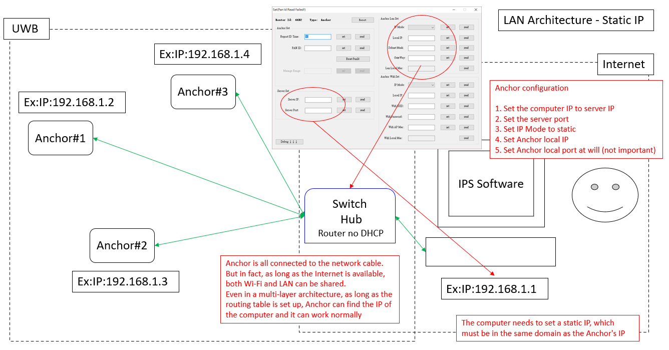
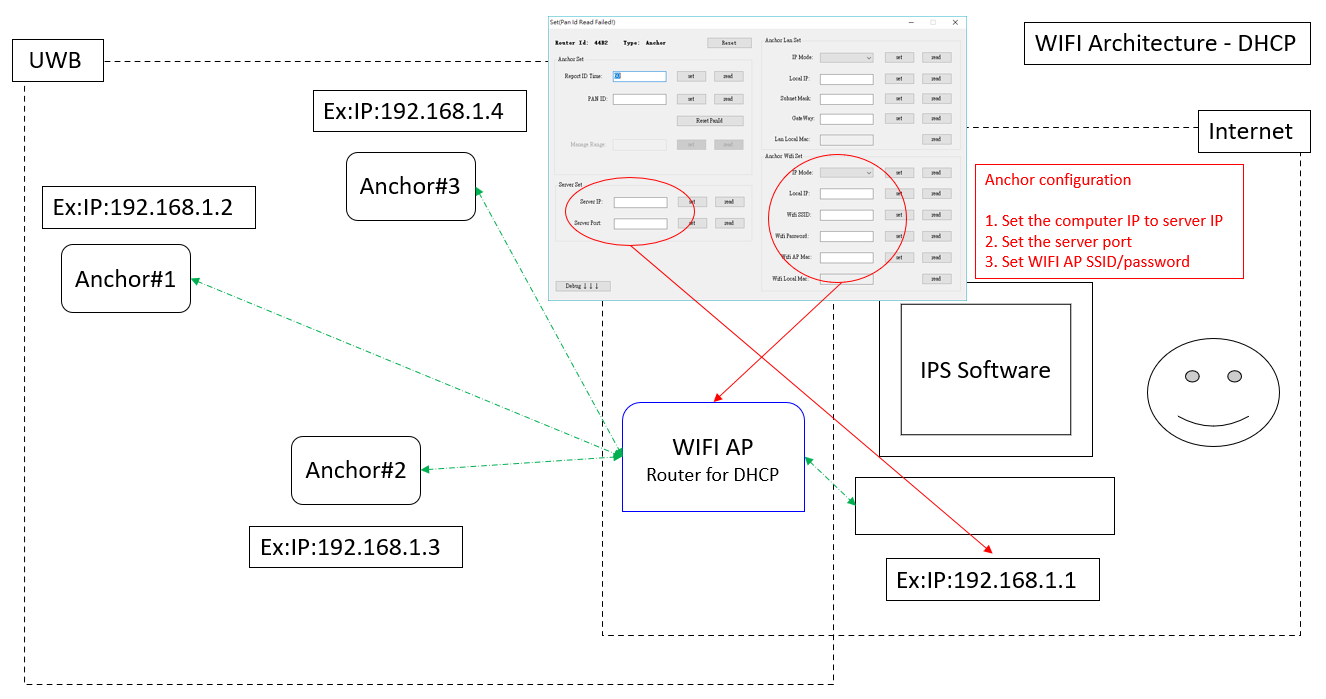
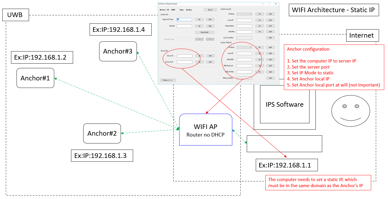
C、 Network Architecture and Parameter Configuration
UWB anchor can use WIFi or Lan to connect to internet, we use the same domain as example below to explain method of setting for possible situations and precautions.
1. WIFI,Configure DHCP
2. WIFI,Configure static IP
3. LAN,Configure DHCP
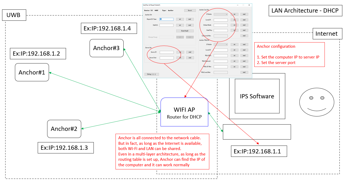
4. LAN,Configure static IP